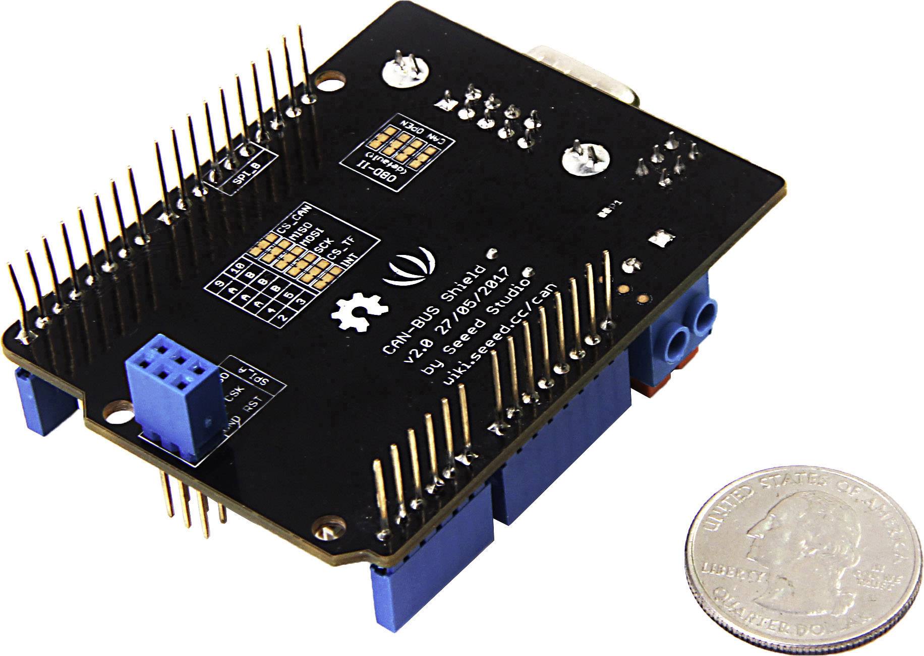
- #Seeed can bus shield v2 how to#
- #Seeed can bus shield v2 zip file#
- #Seeed can bus shield v2 code#
- #Seeed can bus shield v2 zip#
When connecting with putty you can log all incomming data to file as explained in the screenshot from the previous step.
#Seeed can bus shield v2 how to#
Hit the upload button to upload the sketch.įrom here you need to figure out how to detect the messages, such as turning on lightts, open windows ect ect. Serial.println("Init CAN BUS Shield again") Serial.println("CAN BUS Shield init fail") Serial.println("CAN BUS Shield init ok!") INT32U canId = 0x000 unsigned char len = 0
#Seeed can bus shield v2 code#
The CAN-BUS Shield library comes with a working example, it does not include getting the CAN-ID which is quite important to know when analysing the data, So i modified it slightly to include the ID also to seperate all values with a comma so that you can use it as a csv file.Ĭopy and paste the below code into your Arduino Sketch Editor.
#Seeed can bus shield v2 zip#
Tip: You might have to rename the zip as the Arduino IDE does not like unusual characters, so maybe try canbus.zip instead of can-bus.zip
#Seeed can bus shield v2 zip file#
In the Arduino Editor Select Sketch -> Import Library -> Add Library and then point it to the Zip file you downloaded, (No need to unzip the contents it can be imported as is. I get more messages on init but the arduino keeps silent when data is received.First of all you need the Seeed CAN-BUS Shield’s Library downloadable at GIT-HUB After downloading the CAN-BUS Library you need to import it into your Arduino Libraries folder. I have also turned the debug mode on, in the CanBus lib I have tried other configurations for this speed but with no success. I have been wondering whether the config was right for the 200kbps speed so I installed the Chinese tool mentioned on the wiki page.įor my speed 200kbps, the lib config is : #define MCP_16MHz_200kBPS_CFG1 (0x01) Should I anyway get a clear message from time to time? I’m not getting any. Sometimes it’s a bit noisy, in that case, the oscillo cannot decode, but most of the time it is successful. The only difference I can see is that my device signal is not as clean as my car’s signal. I use exactly the same settings on my oscillon (except for speed) to decode both messages. I have compared my car’s and my devices messages and they look really very similar. The bit time is about 5 micro sec, the oscilloscope auto-configured itself to 200kbps.

My oscilloscope decodes the can bus messages with no difficulties. I have a picoscope oscilloscope which can decode CAN BUS messages. I got it working the right way and the Arduino started displaying a message. To be sure to be doing things well, I have plugged the shield/arduino to my car.

The Rx led blinks when receiving data, I have signal on pin 4 of MCP2551, but nothing is displayed. This bus inits well but receives nothing. I’m using the receive_check example provided with the lib. I have plug the bus ground to the shield ground. I have cut the P1 jumper and checked the impedance is still 60 ohm when wiring on the screw terminal. The impedance between canh and canl is 60ohm. I have an undocumented bus running at 200kps (it’ not a car bus) that I need to sniff, there are 3 devices on the bus. I have purchased a Seeed Studio Can Bus Shield V1.2 and I’m having problems listening to a bus at 200kbps but I had success listing to my car's bus.


 0 kommentar(er)
